| Features |
Starter
€ 59.00
/ month
billed annually |
Advanced
€ 329.00
/ month
billed annually |
Professional
€ 499.00
/ month
billed annually |
|---|---|---|---|
Features |
|||
|
MEP Model Creation (Heating & Cooling) For example:
|
Yes | Yes | Yes |
|
Concept in Early Design Phases For example:
|
Yes | Yes | Yes |
|
Collaboration Tools For example:
|
Yes | Yes | Yes |
|
View Creator and View Control For example:
|
Yes | Yes | Yes |
|
Storey Table For example:
|
Yes | Yes | Yes |
|
Visibility Control For example:
|
Yes | Yes | Yes |
|
Task Management For example:
|
Yes | Yes | Yes |
|
Family and Library Manager For example:
|
Yes | Yes | Yes |
|
Industry Families via CAD Browser For example:
|
Yes | Yes | Yes |
|
Parameter Manager and Classification Tool For example:
|
Yes | Yes | Yes |
|
Collision Checker For example:
|
Yes | Yes | Yes |
|
Building Analysis For example:
|
No | Yes | Yes |
|
Heat Load Calculation For example:
|
No | Yes | Yes |
|
Dynamic Cooling Load Calculation For example:
|
No | Yes | Yes |
|
Dimensioning of Radiators & Heating Convectors For example:
|
No | Yes | Yes |
|
Dimensioning of Cooling Convectors For example:
|
No | Yes | Yes |
|
Dimensioning of Panel Heating For example:
|
No | Yes | Yes |
|
Dimensioning of Panel Cooling For example:
|
No | Yes | Yes |
|
Automatic Drawing of dimensioned Components For example:
|
No | Yes | Yes |
|
Automatic Detection of the Heating Pipe Network For example:
|
No | No | Yes |
|
Automatic Detection of the Cooling Pipe Network For example:
|
No | No | Yes |
|
Heating Pipe Network Calculation with Redimensioning For example:
|
No | No | Yes |
|
Cooling Pipe Network Calculation with Redimensioning For example:
|
No | No | Yes |
|
Hydraulic Balancing of complex Systems For example:
|
No | No | Yes |
|
Bill of Quantities including Article Numbers For example:
|
No | No | Yes |
|
Free Access to Online Tutorials
|
Yes | Yes | Yes |
Heating & Cooling Solutions for Revit
Editions
Videos
Description
LINEAR workflow for heating and cooling design with Autodesk Revit
Concept phase
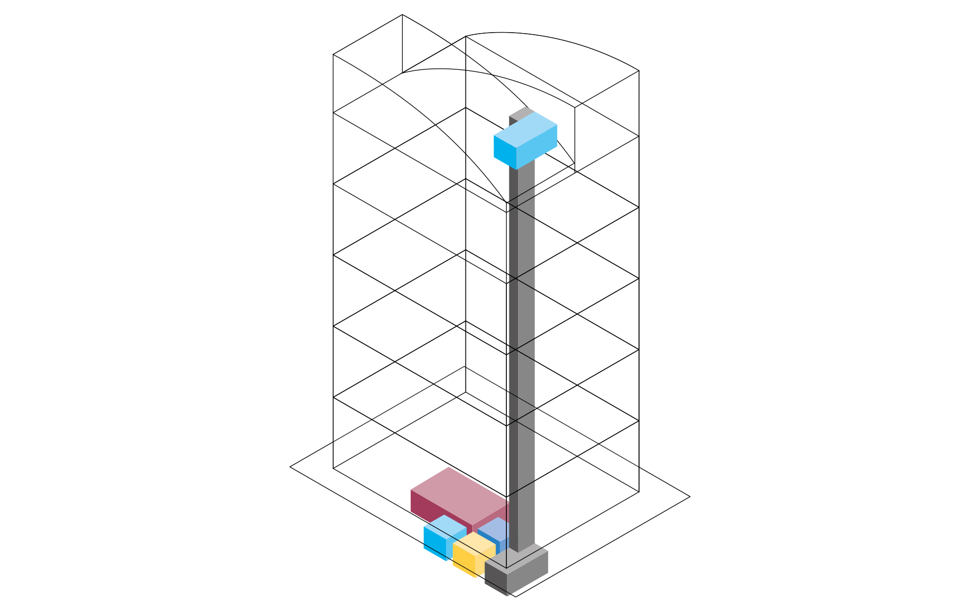

Input: Concept structure of the architecture with rooms, floors and functional areas
Output: Located space requirements for technical rooms and pipeline corridors
Work steps:
- Workflow for a collaborative early design phase planning
- Creation of a concept design on the basis of the requirements planning
- Conceptual space design (Provision for spaces)
- Localization and pre-dimensioning of technical equipment rooms
- Localization and pre-dimensioning of the pipeline corridors
- Cross section editor for the pipeline corridor concept
- Generate pipe and duct elements from corridor concept
Derivation of the thermal model
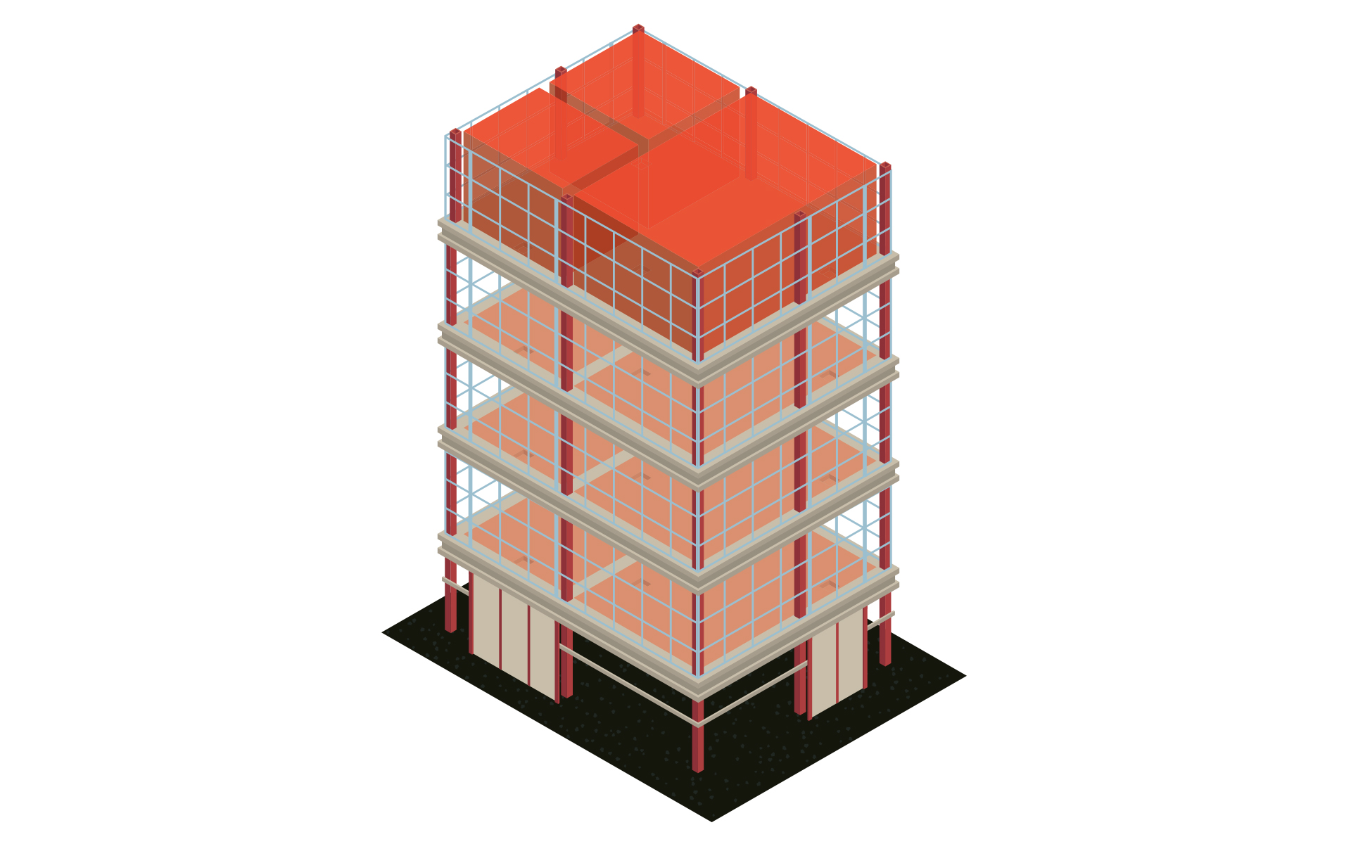

Input: Architecture model or plan
Output: Model for further MEP design including levels, zones & MEP rooms
Work steps:
- Transfer of all relevant floor levels
- Automatic creation of views and plans
- Zoning and creation of MEP rooms
- Enrichment of the model with relevant information
- Parameter management for the assignment of parameters used in the project
- Optional for 2D templates: Simple rebuild of the building in 3D
Building analysis, heating and cooling load calculation
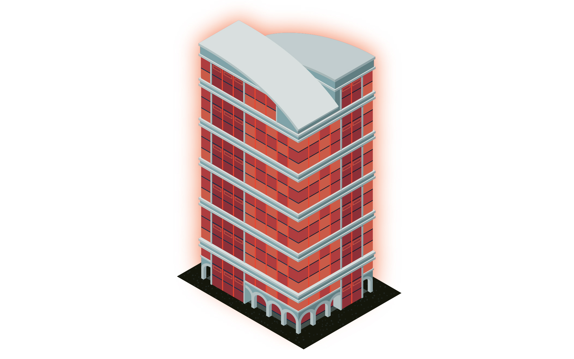

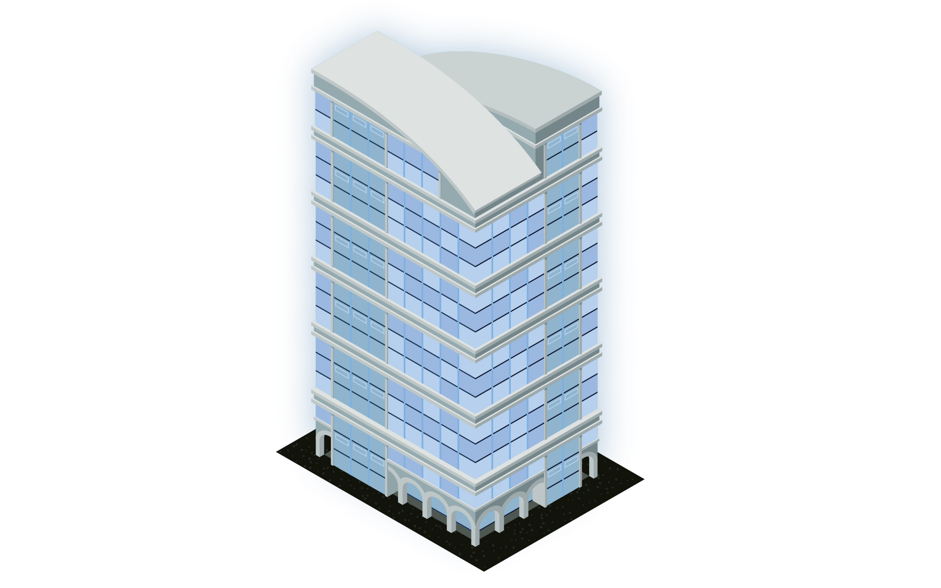

Input: Model for the MEP design including levels, zones & MEP rooms
Output: Calculated heat & cooling load
Work steps:
- Transfer of all relevant floor levels
- Automatic creation of views and plans
- Zoning and creation of MEP rooms
- Enrichment of the model with relevant information
- Parameter management for the assignment of parameters used in the project
- Optional for 2D templates: Simple rebuild of the building in 3D
Radiator, convector, panel heating & cooling design
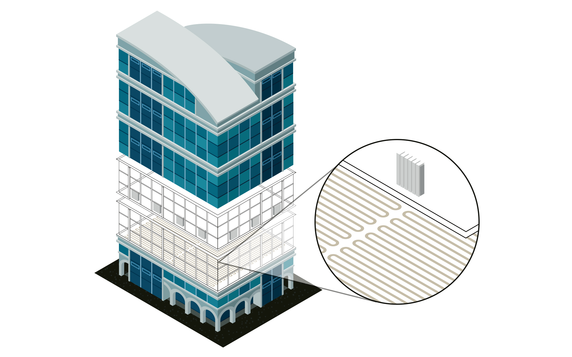

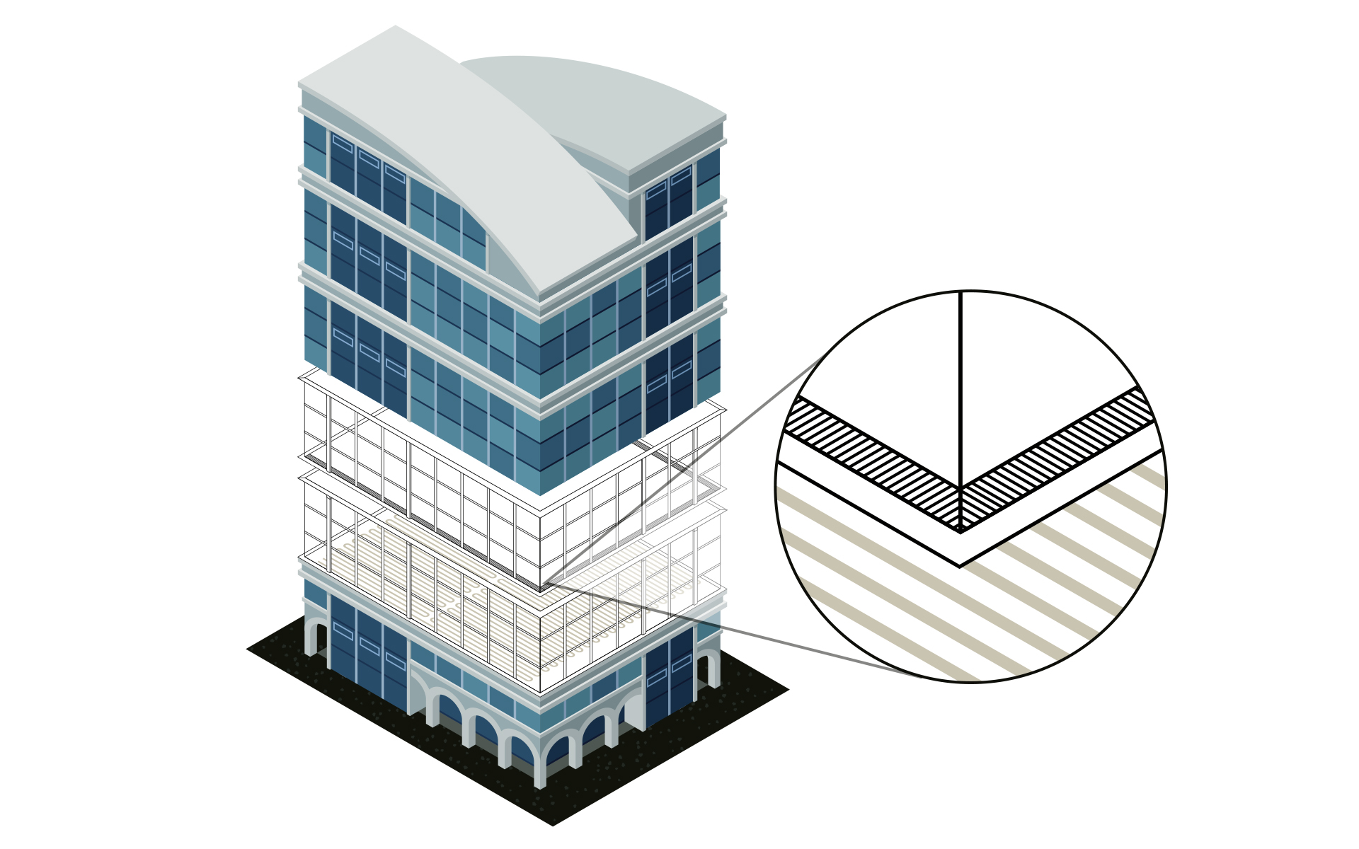

Input: Calculated heat and/or cooling load
Output: MEP model with dimensioned heating/cooling components
Work steps:
- Dimensioning of radiators, convectors, panel heating or cooling systems on the basis of the heat/cooling load calculation
- Comparison of variants by using verified manufacturer data sets
- Transfer of the dimensioned components into the model
- Optional automatic or manual placement of components
- Bidirectional adjustments either in the model or in the dimensioning
- Transfer of all relevant values into the model
System creation and pipe network calculation
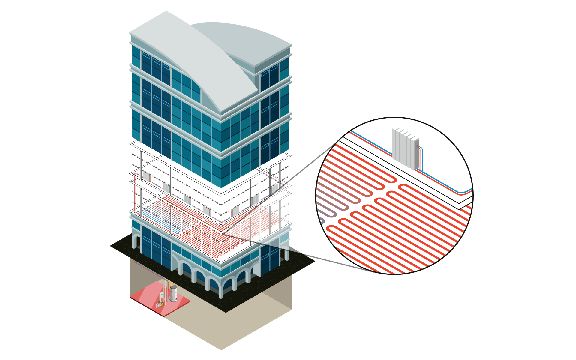

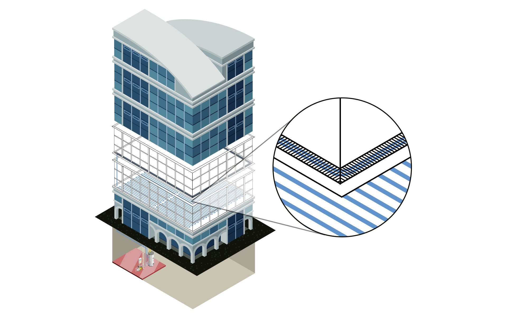

Input: MEP model with dimensioned heating/cooling components
Output: MEP model with optimized systems as well as the finished void planning
Work steps:
- Fast pipe network construction as a single pipe or as parallel pipes
- Automatic connection of all consumers
- Plant design neutral or with the help of extensive manufacturer CAD libraries
- Specification of calculation-relevant specifications (e.g. assignment of pipe materials, settings of valves, specification of insulation and ambient temperatures)
- Comparison of variants by using verified manufacturer data sets (e.g. pipe systems)
- Calculation of existing networks by fixing individual or all dimensions
- Redimensioning of the heating and cooling pipe network on the basis of the calculation
- Colored display of all results directly in the model (LINEAR data coloring)
- Void planning including coordination via BCF and IFC
Labeling, output of model data and results
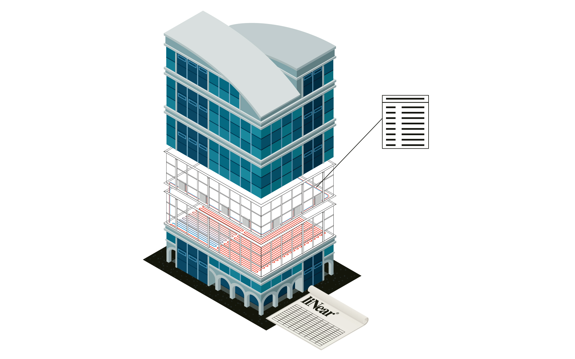

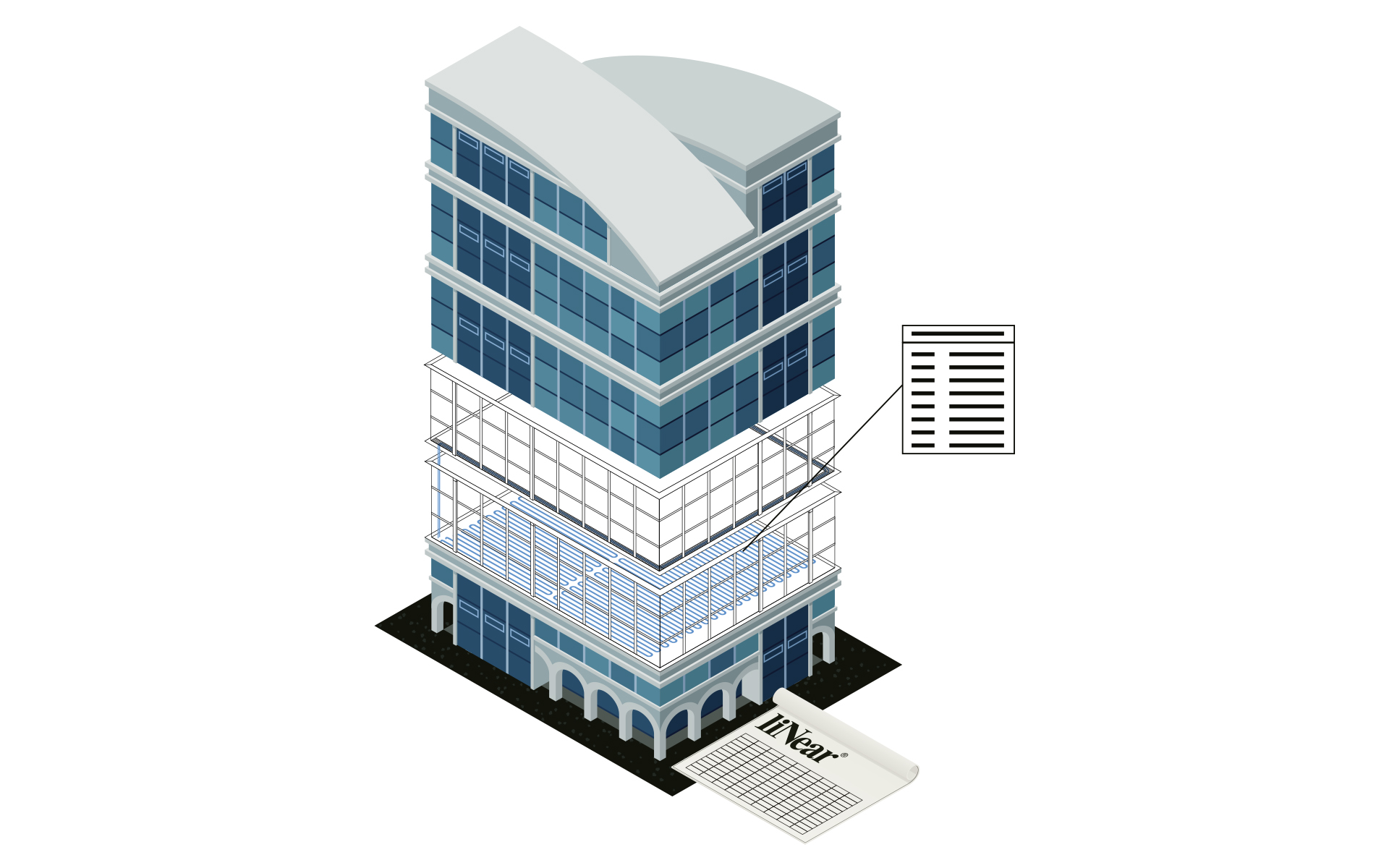

Input: Calculated and optimized heating/cooling pipe network
Output: Final heating/cooling design including model for transfer to the coordination model and calculated results incl. material lists
Work steps:
- Storage of all inputs and calculation results in the model
- Publication of selectable values as shared parameters
- Automatic labeling of the model
- Addition of own parameters and meta information
- Printout of the results in standardized forms
- Transfer of the results and the model in all relevant formats
