| Features |
Starter
€ 59.00
/ month
billed annually |
Advanced
€ 199.00
/ month
billed annually |
Professional
€ 299.00
/ month
billed annually |
Professional 3D
€ 499.00
/ month
billed annually |
|---|---|---|---|---|
Features |
||||
|
MEP Model Creation (Heating, Cooling & Gas) For example:
|
Yes | Yes | Yes | Yes |
|
Scheme generator (Heating + Gas) Create the fastes schemes in the industry with the powerfull scheme generator For example:
|
Yes | Yes | Yes | Yes |
|
Storey table For example:
|
Yes | Yes | Yes | Yes |
|
Visibility Control For example:
|
Yes | Yes | Yes | Yes |
|
Industry Components via CAD Browser For example:
|
Yes | Yes | Yes | Yes |
|
Creation and Preperation of the Architectural Model for Calculations For example:
|
Yes | Yes | Yes | Yes |
|
Building Analysis For example:
|
No | Yes | Yes | Yes |
|
Heat Load Calculation For example:
|
No | Yes | Yes | Yes |
|
Dimensioning of Radiators & Convectors For example:
|
No | Yes | Yes | Yes |
|
Dimensioning of Panel Heating For example:
|
No | Yes | Yes | Yes |
|
Automatic Drawing of dimensioned Components For example:
|
No | Yes | Yes | Yes |
|
Automatic Detection of the Heating Pipe Network For example:
|
No | No | Yes | Yes |
|
Heating Pipe Network Calculation with Redimensioning For example:
|
No | No | Yes | Yes |
|
Hydraulic Balancing of complex Systems For example:
|
No | No | Yes | Yes |
|
Bill of Quantities including Article Numbers For example:
|
No | No | Yes | Yes |
|
Detailed 3D Design (Heating, Cooling, Gas, Potable Water, Waste Water) For example:
|
No | No | No | Yes |
|
Free Access to Online Tutorials
|
Yes | Yes | Yes | Yes |
Heating Solutions for AutoCAD
Editions
Videos
Description
LINEAR workflow for heating design with Autodesk AutoCAD
Schematic design
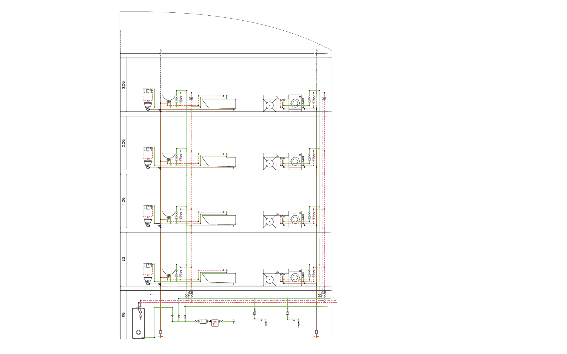

Input: Supply requirements for the building
Output: Calculable scheme design
Work steps:
- Create storey table
- Manual scheme creation with toolbars and specific editing commands
- Scheme generator for drag and drop and automated drawing
Derivation of the thermal model
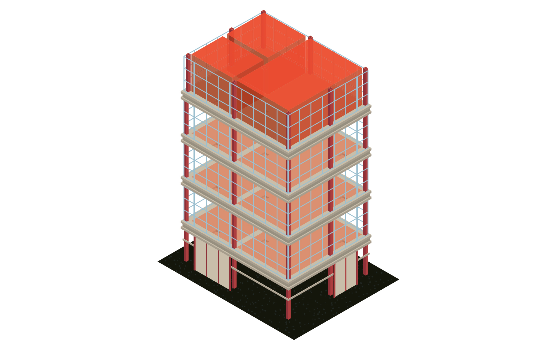

Input: Architecture plan
Output:Model for further MEP design including levels and rooms
Work steps:
- Referencing DWGs, DXFs or PDFs from the architect
- Create storey table
- Create and enrich the architecture with room data
Building analysis and heating load calculation
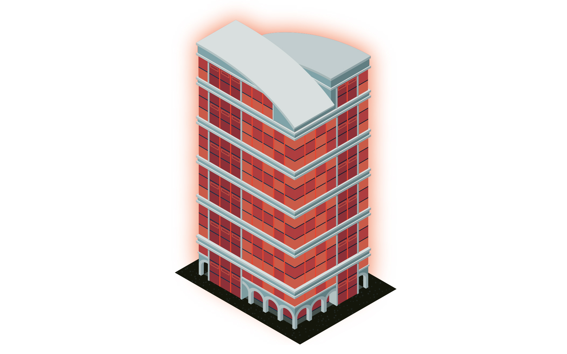

Input: Architecture model with additional information for analysis
Output: Calculated heat load
Work steps:
- Powerful building analysis as a basis for the heat load calculation
- Automatic mapping of the building structure (building parts, storeys and rooms)
- Identification and collaborative correction of modeling errors in exchange with the architect
- U-value calculation and addition of any missing calculation parameters
- Automatic heat load calculation for the project, the storeys as well as all rooms
- Transfer of all relevant values into the model
Radiator and panel heating dimensioning
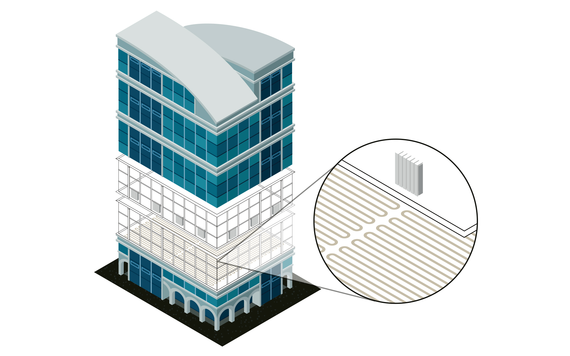

Input: Calculated heat load
Output: MEP model with dimensioned heating components
Work steps:
- Dimensioning of radiators, convectors or panel heating systems on the basis of the heat load calculation
- Comparison of variants by using verified manufacturer data sets
- Transfer of the designed components into the model
- Optional automatic or manual placement of components
Create system in the isometry or floor plan
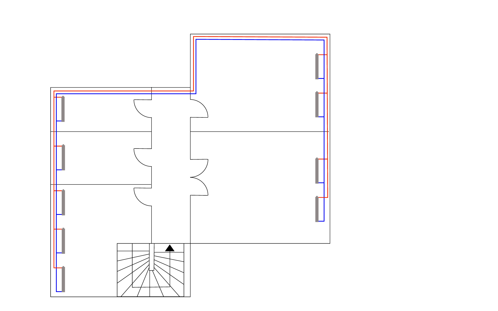

Input: MEP model with dimensioned heating components
Output:MEP Model with a calculable network (isometric or floor plan)
Work steps:
- 2D or isometric pipe network design using time-saving construction commands
- Automatic connection of all consumers
- System design in a neutral way or with the help of extensive manufacturer CAD libraries
Create system in 3D
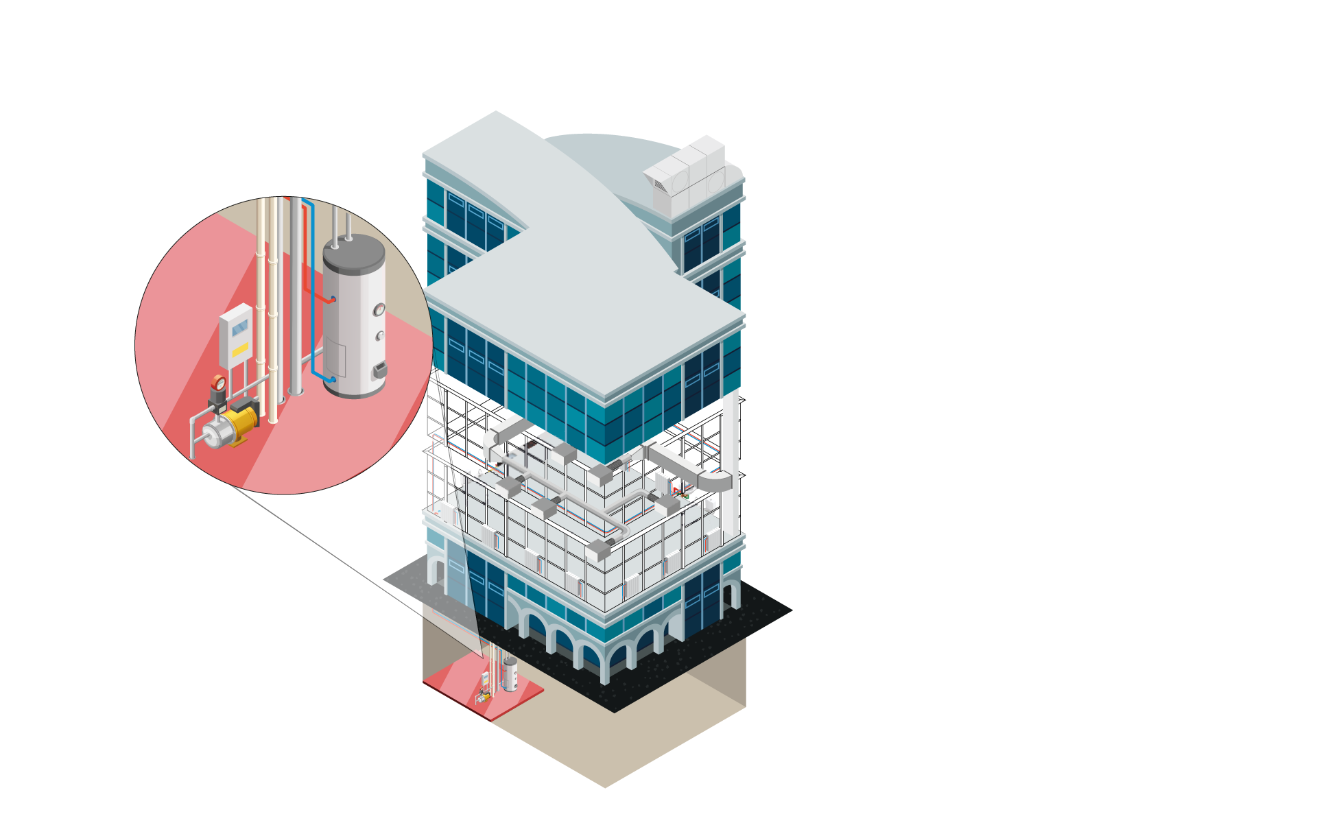

Input: MEP model with dimensioned heating components
Output: Detailed 3D model
Work steps:
- Detailed pipe design
- Automatic routing functions with preview of possible alternatives
- System design in a neutral way or with the help of extensive manufacturer CAD libraries
- Subsequent placement of components with matching transitions and flanges
- Automatic bolting of the entire construction (bolts, nuts, washers) with complete transfer to the parts list
- Pre-define insulation materials and show/hide them with transfer to the parts list
- Real-time collision check
- Manually or automatically assigned item numbers
- Material lists, parts lists with article numbers, sawing lists for pipes, position lists
Heating pipe network calculation
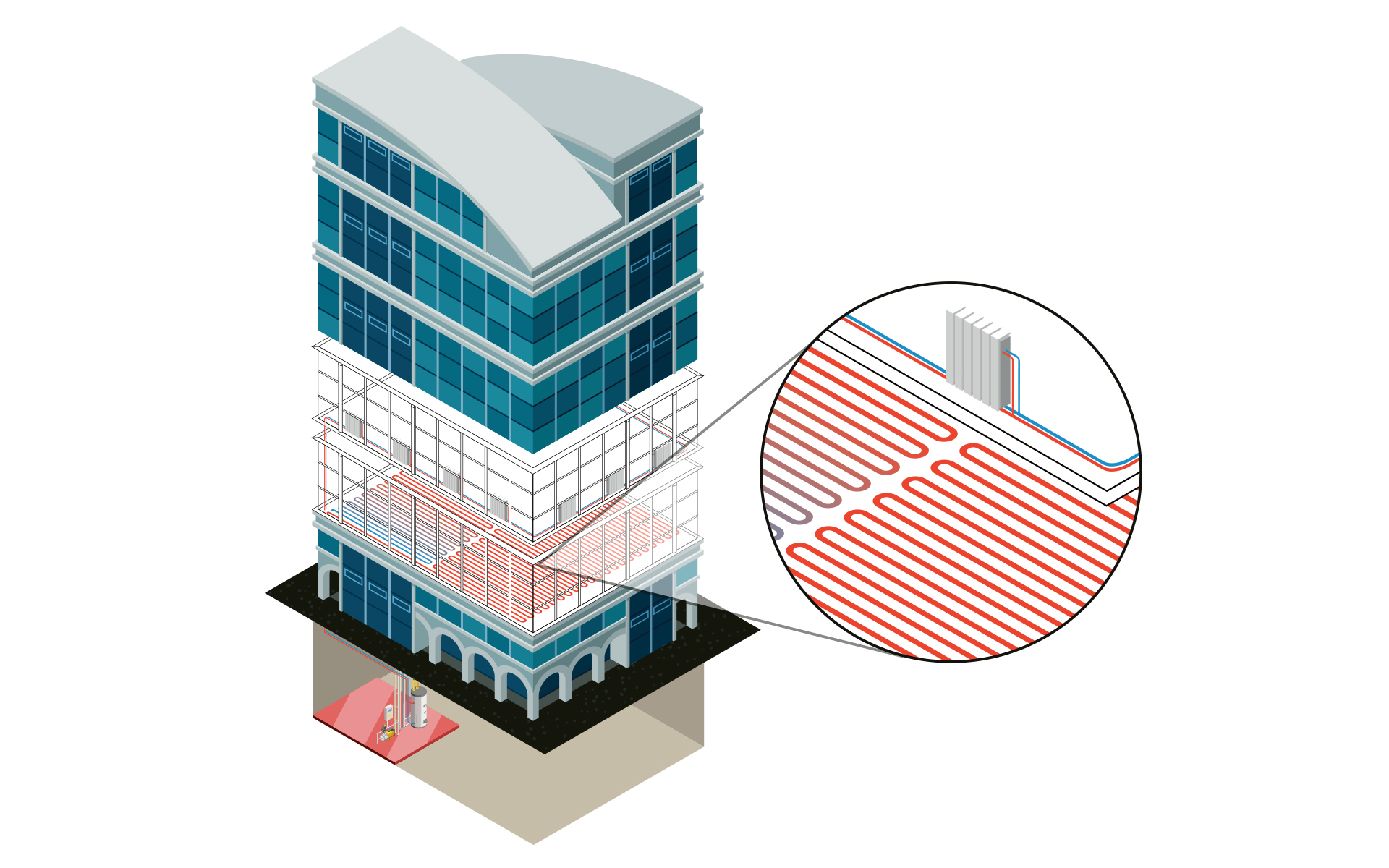

Input: Schematic, 2D or 3D model
Output: MEP model with optimized heating system (schematic, 2D or 3D)
Work steps:
- Specification of calculation-relevant specifications (e.g. assignment of pipe materials, settings of valves, specification of insulation and ambient temperatures).
- Comparison of variants by using verified manufacturer data sets (e.g. pipe systems)
- Calculation of existing networks by fixing individual or all dimensions
- Redimensioning of the heating pipe network based on the calculation
- Colored display of all results directly in the model
- Automatic 3D generation during system creation in 1-stroke (step 5 - variant 1)
Labeling, output of model data and results
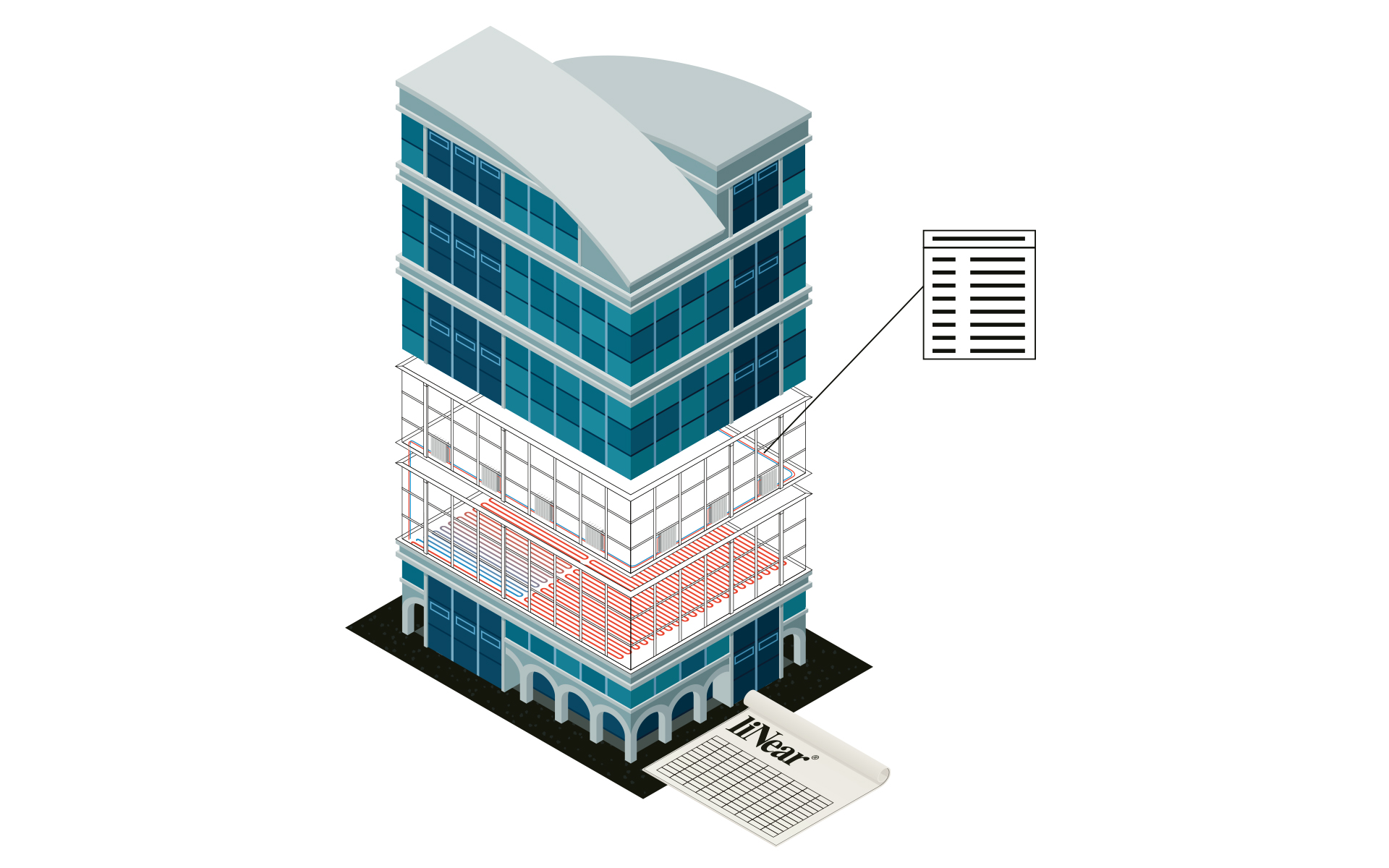

Input: Calculated and optimized heating pipe network
Output: Final heating design including model for transfer to the coordination model and calculated results incl. material lists
Work steps:
- Saving of all inputs and calculation results in the model
- Publication of selectable values as component data
- Automatic labeling of the model
- Addition of own parameters and meta information
- Printout of the results in standardized forms
- Transfer of results and model in all relevant formats
