| Features |
Starter
€ 59.00
/ month
billed annually |
Professional
€ 249.00
/ month
billed annually |
Professional 3D
€ 399.00
/ month
billed annually |
|---|---|---|---|
Features |
|||
|
MEP Model Creation (Ventilation) For example:
|
Yes | Yes | Yes |
|
Storey table For example:
|
Yes | Yes | Yes |
|
Visibility Control For example:
|
Yes | Yes | Yes |
|
Industry Components via CAD Browser For example:
|
Yes | Yes | Yes |
|
Automatic Detection of the Air Duct Network For example:
|
No | Yes | Yes |
|
Air Duct Network Calculation with Redimensioning For example:
|
No | Yes | Yes |
|
Flow mechanical Balancing of complex Systems including Sound Level Calculation For example:
|
No | Yes | Yes |
|
Bill of Quantities including Article Numbers For example:
|
No | Yes | Yes |
|
Detailed 3D Design (Ventilation) For example:
|
No | No | Yes |
|
Free Access to Online Tutorials
|
Yes | Yes | Yes |
Ventilation Solutions for AutoCAD

Ventilation Solutions for AutoCAD
Design and calculate ventilaton systems in Autodesk AutoCAD
SKU
VEAC
€ 708.00
Editions
Videos
Loading...
Description
LINEAR Workflow for ventilation design with Autodesk AutoCAD
Schematic design
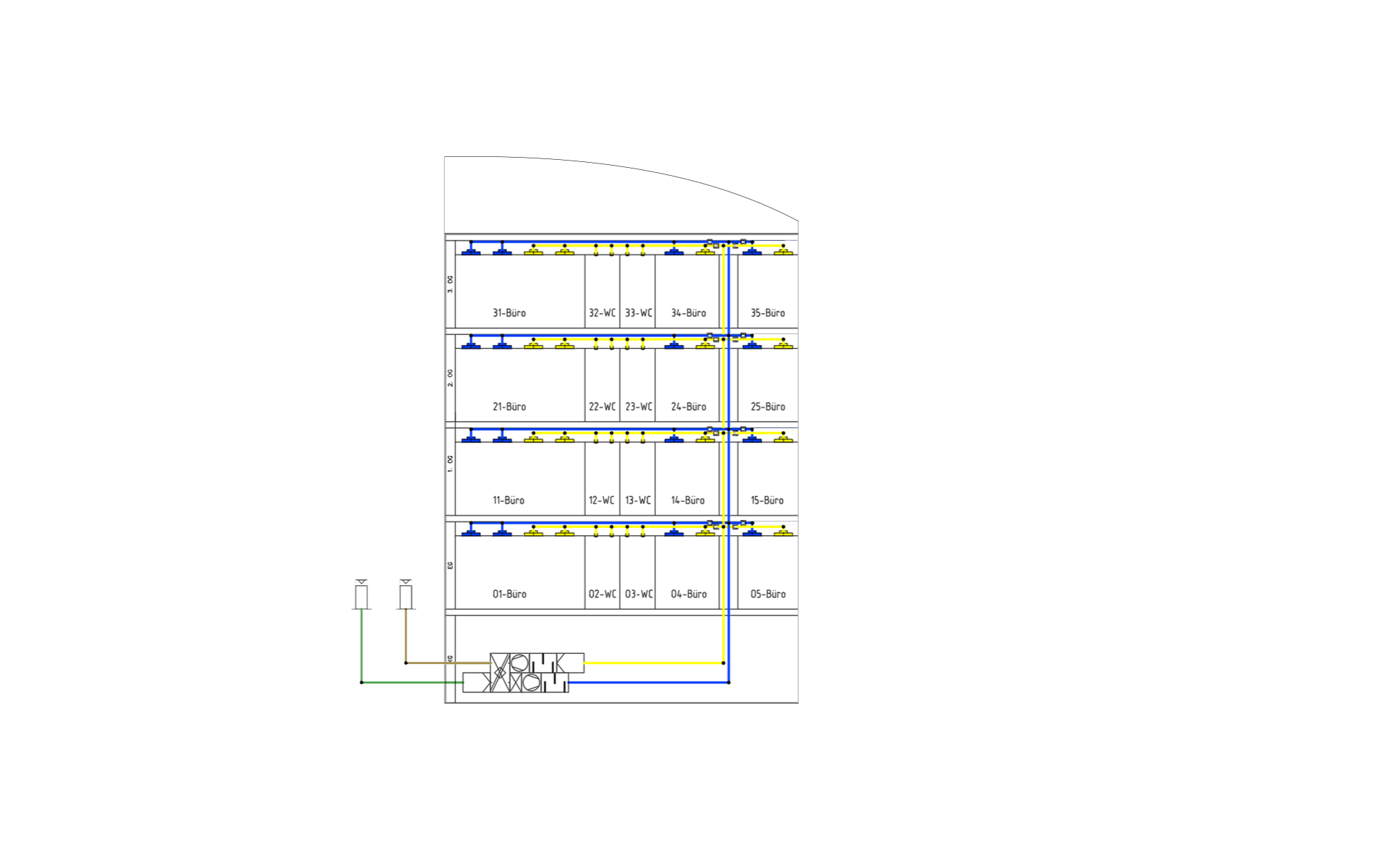
Input: Supply requirements for the building
Output: Calculable scheme design
Work steps:
- Create storey table
- Manual scheme creation with toolbars and specific editing commands
Architecture as construction basis
Input: Architecture plan
Output: Model for further MEP design including levels and rooms
Work steps:
- Referencing DWGs, DXFs or PDFs from the architect
- Create storey table
- Create and enrich the architectural model for further construction
Determine volume flows, select outlets and configure the air handling unit
Input: Model for the MEP design including levels and rooms
Output: HVAC model with designed outlets and air handling unit
Work steps:
- Powerful building analysis as a basis for the cooling load calculation
- Automatic mapping of the building structure (building parts, storeys and rooms)
- Identification and collaborative correction of modeling errors in exchange with the architect
- U-value calculation and addition of any missing calculation parameters
- Dynamic cooling load calculation for the project, the storeys as well as all rooms
- Transfer of all relevant values into the model
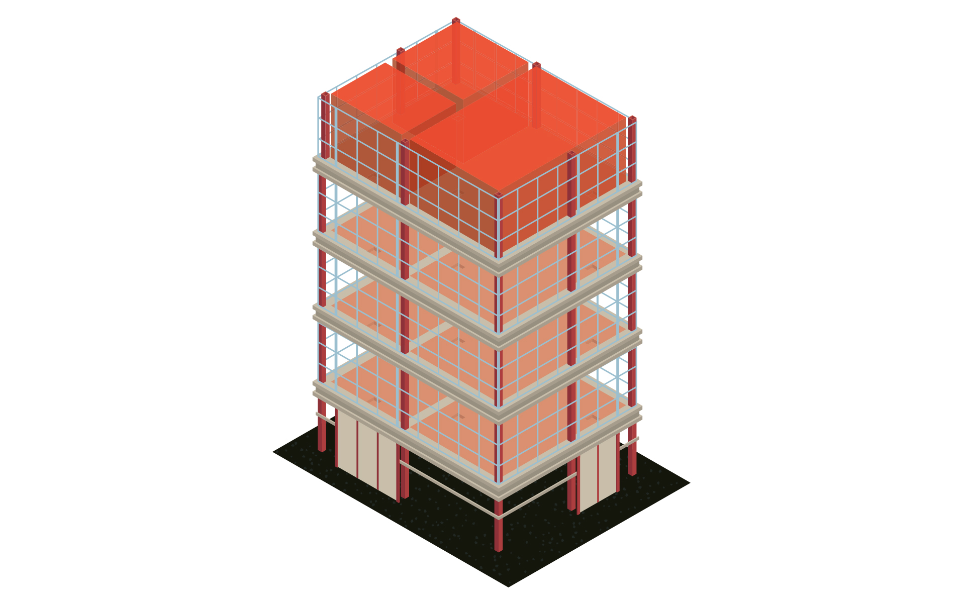
Create system in the isometry or floor plan
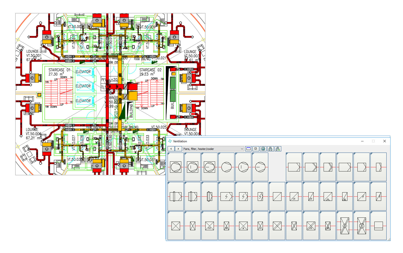
Input: HVAC model with placed outlets and air handling unit
Output:MEP Model with a calculable network (isometric or floor plan)
Work steps:
- 2D or isometric duct network design using time-saving construction commands
- Automatic connection of all outlets
- Insertion of built-in parts from neutral or manufacturer libraries (e.g., silencers or fire dampers)
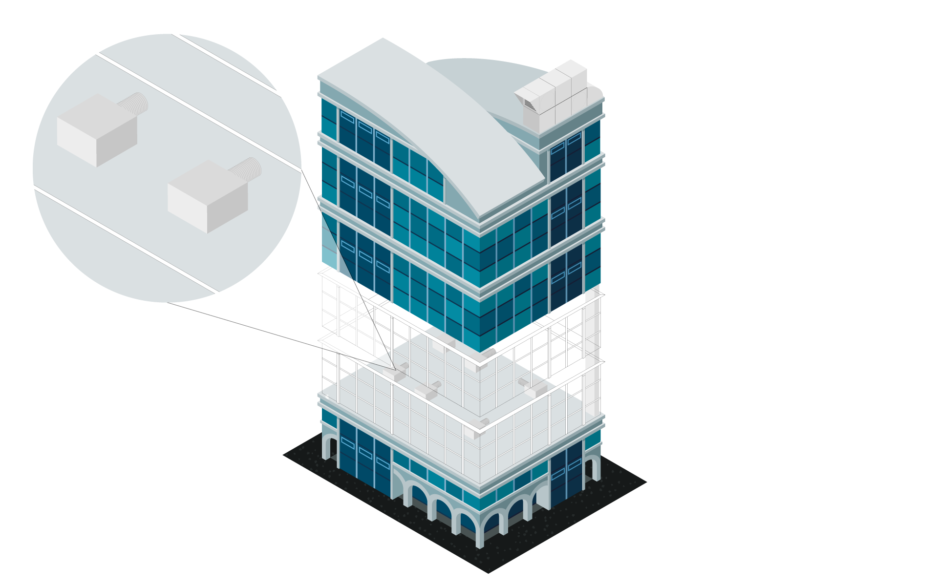
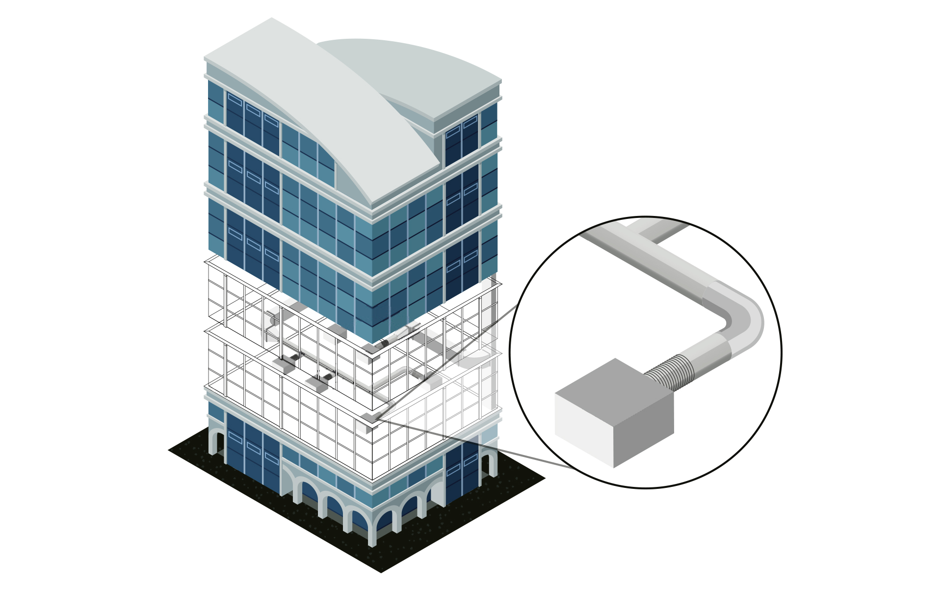
Create system in 3D

Input:HVAC model with placed outlets and air handling unit
Output: Detailed 3D model
Work steps:
- Automatic routing functions with preview of possible alternatives
- System design neutral or with the help of extensive manufacturer CAD libraries
- Subsequent placement of components with matching transitions and flanges
- Automatic bolting of the entire construction (bolts, nuts, washers) with complete transfer to the parts list
- Pre-define insulation materials and show/hide them with transfer to the parts list
- Real-time collision check
- Manually or automatically assigned item numbers
- Duct and insulation measurement, compilation of frame connectors with profiles and elbows, parts and position lists including all fittings
Air duct network calculation
Input: Schematic, 2D or 3D model
Output: HVAC model with designed outlets and air handling unitmodel with optimized ventilation system (schematic, 2D or 3D)
Work steps:
- Air duct network calculation (pressure loss calculation, flow-mechanical balancing, sound calculation).
- Support of several systems at the same time and many special constructions (e.g. cross-section splitting at grilles, several fans)
- Calculation of existing networks by fixing single or all dimensions
- Redimensioning of the air duct network based on the calculation
- Colored display of all results directly in the model (LINEAR Data Coloring)
- Transfer via e-klimaX directly to the air duct manufacturer
- Automatic 3D generation during system creation in 2D (step 4 - variant 1)
Labeling, output of model data and results
Input: Calculated and optimized ventilation network
Output: Final ventilation design including model for transfer to the coordination model and calculation results incl. material lists
Work steps:
- Saving of all inputs and calculation results in the model
- Publication of selectable values as component data
- Automatic labeling of the model
- Addition of own parameters and meta information
- Printout of the results in standardized forms
- Transfer of results and model in all relevant formats