Ventilation Solutions for Revit

Design and calculate ventilation systems in Autodesk Revit
SKU VERE

Editions

Starter
€ 59.00 / month

billed annually

Professional
€ 249.00 / month

billed annually

Features

MEP Model Creation (Ventilation)

For example:

  • Pipe command including system class determination
  • Automatic connection of ducts including necessary transitions (auto-routing)
  • Automatic T-piece connection
  • Configurator for air handling units
  • Offset command to resolve collisions
  • Wide variety of air outlets, protective gratings and components for round, oval and rectangular ducts such as sound absorbers, fire dampers, fans and volume flow rate controllers (generic and manufacturer-specific)
  • Configurator of parallel ducts/pipes for routing multiple ducts and pipes at once
  • Automatic Labeling
Yes Yes

Concept in Early Design Phases

For example:

  • Tools for predimensioning technical equipment rooms for all disciplines
  • Drag&Drop Editor for defining cross sections of the pipeline corridors
  • Placing of predimesnioned pipeline corridors
  • Communication of the space requirements via IFC ("Provisions for Voids")
Yes Yes

Collaboration Tools

For example:

  • Void planning with tools for collaboration with architects, structural engineers and other participants
  • Report and task manager with BCF and IFC Ex- & Import
Yes Yes

View Creator and View Control

For example:

  • View creation assistant for 3D views, floor plans, ceiling plans and area plans
  • Quick 3D selection box command
  • Quick working section commands
  • Automatic sorting and assignment of views
  • Suggestions for best suitable views
  • Automatic LOG assignement to views
  • View filter
Yes Yes

Storey Table

For example:

  • Automatic import of storeys from the architectural model
  • Control of the storey in the Construction level / offset (+/-) section
  • Easy Creation of storeys and work levels
  • Separate storey table for mutliple building parts (e.g. for split levels)
Yes Yes

Visibility Control

For example:

  • One click visibility control for building parts
  • One click visibility control for storeys
  • One click visibility control for disciplines
  • One click visibility control for component groups (e.g. systems, insulations, etc.)
Yes Yes

Task Management

For example:

  • Assigning of responsibilities for automatic (e.g. from the calculations) or manually created tasks
  • Set of deadlines and priorities for tasks
  • Status tracking of tasks
  • Definition of given workflows for the resolution of tasks
  • Adding of Screenshots, comments, positions to tasks
  • Sharing and assignment of tasks to participants via BCF
Yes Yes

Family and Library Manager

For example:

  • Providing of all necessary components for your project centrally
  • Components or configurators suitable for the active discipline
  • Filtered by active discipline, used in project and locations (local or folder in the network)
  • Sorted in component groups for quick orientation
  • Multiple placing comands for families (place, replace, replace all, place on grid)
  • Integration of own family libraries
  • Intelligent search function
  • Pick and place again of a component in the model
Yes Yes

Industry Families via CAD Browser

For example:

  • Extensive CAD libraries with approved components of our wide range of industry partner
  • More than 6 billion possible components and component combinations
  • Direct placement of original manufacturer components into your model
  • Multiple placing modes (place, replace, replace all of a kind)
  • Configurators for complex component combinations (e.g. cascade systems)
  • Including technical and commercial data (e.g. article numbers and packaging units)
  • Detection and consideration in the network calculations
Yes Yes

Parameter Manager and Classification Tool

For example:

  • Assigning of liNear parameters to your own shared parameters in a project-dependent mapping table
  • Search and filter functions for mapping or overwrite of parameters
  • Loading and Saving of predefined project standards
  • Assignment of classification parameter to components and model elements to fill it with values
  • Structure the classification of component groups in the IFC export
  • Classification components related to cost groups for precise cost estimations
Yes Yes

Collision Checker

For example:

  • Detection and display of collisions of any kind within a project or between several projects
  • Collision check between Architecture and all disciplines
  • Collision check between two discipline or one discipline with the architecture
  • Collision check between single or multiple categories (e.g. walls and pipes)
  • Collision check between single or multiple systems (e.g. Gas and exhaust air)
  • Automatic creation of tasks for each collision in the Report and Task Tab
  • Saving and Loading of predefined configurations
Yes Yes

Automatic Detection of the Air Duct Network

For example:

  • Detection of drawn ducts and components directly in the model and analysis of the system
  • Detection of all integrated components such as air outlets, fans or volume flow regulators
  • Consideration of technical datas integrated in the model
  • Detection of drawn dimension for the optionally consideration in the network calculation
  • Easy mapping of foreign components for the consideration in the network calculation
No Yes

Air Duct Network Calculation with Redimensioning

For example:

  • Automatic calculation and dimensioning of all components in the ventilation network
  • Dynamically determined zeta values for a detailed calculation of the drag coefficients
  • Detailed setting options, e.g. for dimensioning limits (maximum heights, etc.)
  • Flow mechanical balancing
  • Integrated sound level calculation
  • Determination and variant comparison of duct materials including original manufacturer data sets with reals product properties
  • Calculation directly in the model incl. redimensioning
  • Calculation of multiple systems in one model
  • Selection of suitable (manufacturer) components based on the calculation results
  • Saving of values directly in the model with optional consideration in the IFC export
  • Visualization of results using liNear Data Coloring (dimensions, materials, velocities, unfavorable flow path and many more)
No Yes

Flow mechanical Balancing of complex Systems including Sound Level Calculation

For example:

  • Flow mechanical Balancing with transfer of performance data from real product properties using data sets from leading manufacturers
  • Calculation of multiple systems in one model
  • Determination also of networks with several control levels
  • Consideration not only of the distribution networks, but also the generator part
No Yes

Bill of Quantities including Article Numbers

For example:

  • Clear and comprehensible calculation results as well as complete bill of quantities
  • Detailed parts lists including article numbers and material check
  • Bill of quantities and parts lists in several output formats (Windows printout, Excel, text, UGS, GAEB, ASD)
No Yes

Free Access to Online Tutorials

  • Easy start and education with the liNear tutorials and example projects in the exclusive customer area on our website
Yes Yes

Videos

Description

LINEAR workflow for ventilation design with Autodesk Revit

Concept phase

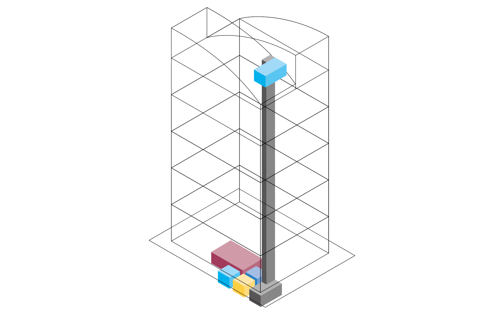
Input: Concept structure of the architecture with rooms, floors and functional areas

Output: Located space requirements for technical rooms and pipeline corridors

Work steps:

  • Workflow for a collaborative early design phase planning
  • Creation of a concept design on the basis of the requirements planning
  • Conceptual space design (Provision for spaces)
  • Localization and pre-dimensioning of technical equipment rooms
  • Localization and pre-dimensioning of the pipeline corridors
  • Cross section editor for the pipeline corridor concept
  • Generate pipe and duct elements from corridor concept

Building model as basis for design

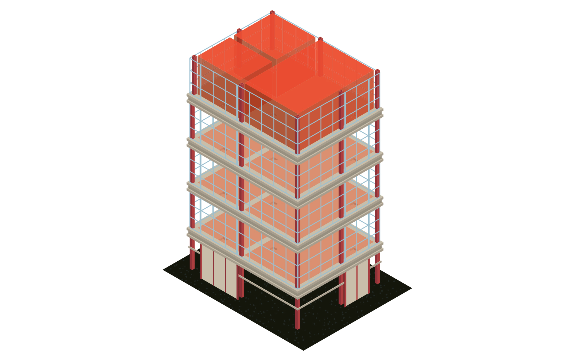
Input: Architecture model or plan 

Output: Model for further MEP design including levels, zones & MEP rooms

Work steps:

  • Easy creation of the MEP model based on the architecture
  • Zoning and creation of MEP spaces
  • Enrichment of the model with relevant information
  • Automatic creation of views and plans 
  • Parameter management for the assignment of parameters used in the project 
  • Optional for 2D templates:  Simple re-entry of the building in 3D

Determine volume flow rate, select outlets and configure the air handling unit

Input: Model for the MEP design including levels, zones & MEP rooms

Output: MEP model with placed outlets and ventilation unit

Work steps:

  • Determination of volume flow rates room by room 
  • Selecting the type and number of outlets and place them
  • Configuring and positioning of the ventilation unit (neutral or manufacturer-specific)

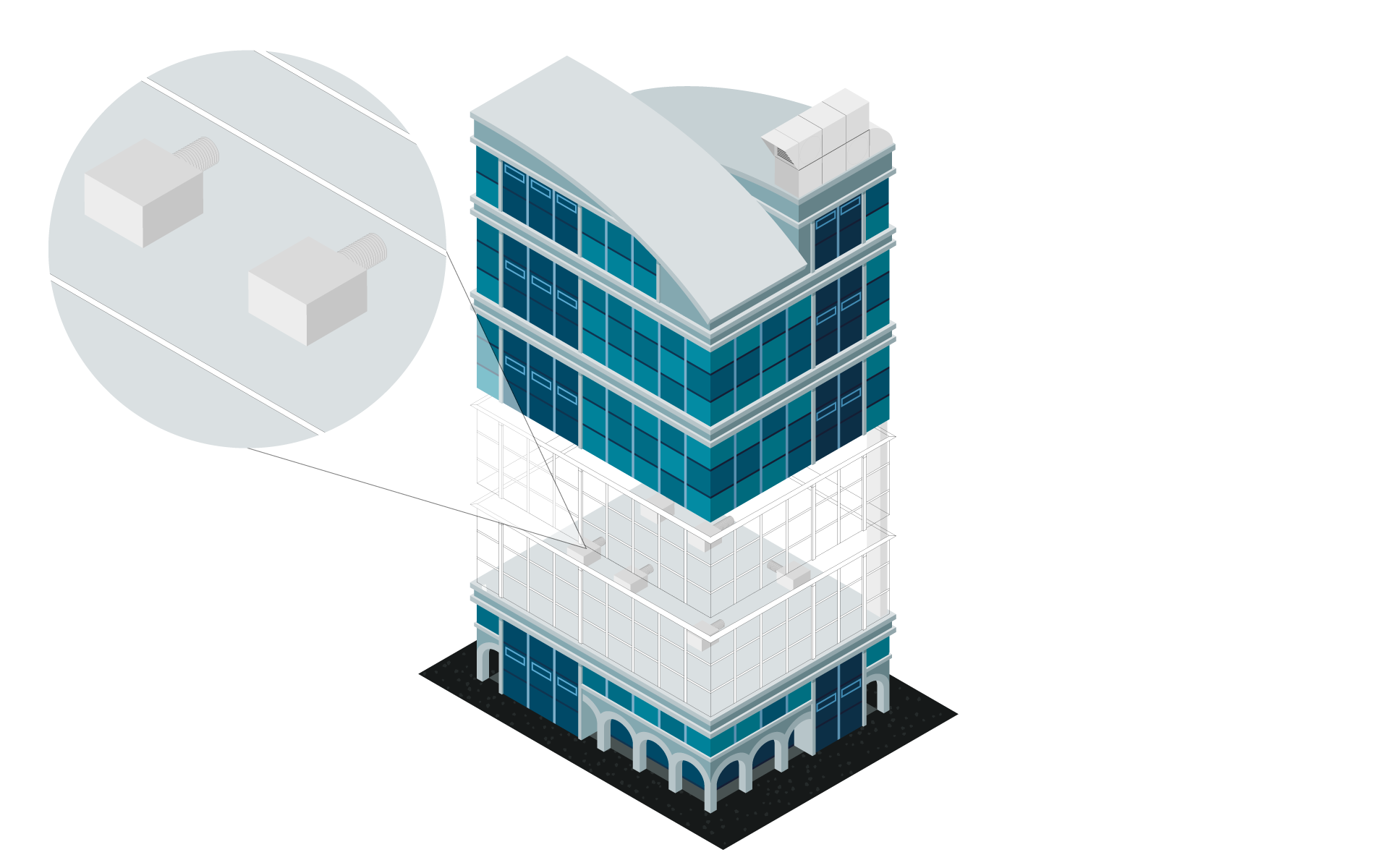
System creation and air duct network calculation

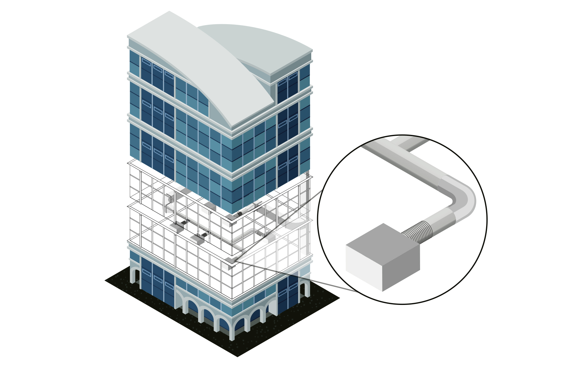
Input: MEP model with placed outlets and ventilation unit

Output: MEP model with optimized systems as well as the finished void planning

Work steps:

  • Fast duct network construction round, oval and rectangular
  • Automatic connection of all outlets
  • Insertion of installation parts from neutral or manufacturer libraries (e.g. silencers or fire dampers)
  • Air duct network calculation (pressure loss calculation, flow mechanical balancing, sound calculation)
  • Support of multiple systems at the same time and many special constructions (e.g. cross-section splitting at weather grilles, several fans) 
  • Calculation of existing networks by fixing choosen or all dimensions
  • Redimensioning of the air duct network based on the calculation
  • Colored display of all results directly in the model (LINEAR data coloring)
  • Void planning including coordination via BCF and IFC
  • Transfer via e-klimaX directly to the air duct manufacturer

Labeling, output of model data and results

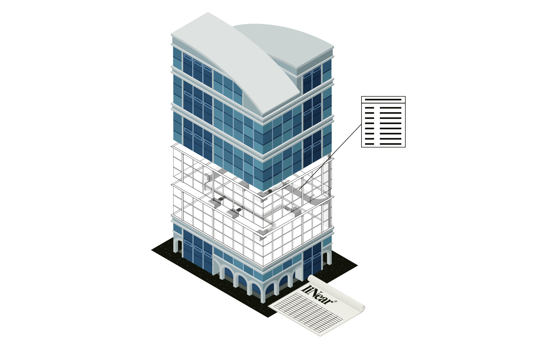
Input: Calculated and optimized air duct network

Output: Final ventilation design including model for transfer to the coordination model and calculated results incl. material lists

Work steps:

  • Storage of all inputs and calculation results in the model
  • Publication of selectable values as shared parameters
  • Automatic labeling of the model
  • Addition of own parameters and meta information
  • Printout of the results in standardized forms 
  • Transfer of the results and the model in all relevant formats