Water Solutions for AutoCAD

Design and calculate potable and waste water systems in Autodesk AutoCAD
SKU WAAC

Editions

Starter
€ 59.00 / month

billed annually

Advanced
€ 149.00 / month

billed annually

Professional
€ 229.00 / month

billed annually

Professional 3D
€ 429.00 / month

billed annually

Features

MEP Model Creation (Potable and Waste Water)

For example:

  • Pipe command including system class determination
  • Automatic connection of pipes including necessary transitions (autorouting)
  • Automatic T-piece connection
  • Pipe offset command to resolve collisions
  • Configurators for tanks and dwelling stations
  • Configurator of parallel pipes for routing multiple pipes at once
  • Automatic Labeling
Yes Yes Yes Yes

Scheme Generator (Potable and Waste Water)

Create the fastes schemes in the industry with the powerfull scheme generator

For example:

  • Generate a complete and calculable scheme with drag and drop
  • Creating schemes even without CAD experience
  • Automatic drawing of scheme Define sections and bows
  • Easy copy of storeys and pipe runs
  • Definition of components (e.g. valves and pumps) already in the generator
  • Use of potable water scheme for creating the waste water scheme and the other way around
  • Saving and importing of existing configurations
Yes Yes Yes Yes

Storey table

For example:

  • Automatic import of storeys from the architectural model
  • Control of the storey in the Construction level / offset (+/-) section
  • Easy Creation of storeys and work levels
Yes Yes Yes Yes

Visibility Control

For example:

  • One click visibility control for building parts
  • One click visibility control for storeys
  • One click visibility control for disciplines
  • One click visibility control for component groups (e.g. systems, insulations, etc.)
Yes Yes Yes Yes

Industry Components via CAD Browser

For example:

  • Extensive CAD libraries with approved components of our wide range of industry partner
  • More than 6 billion possible components and component combinations
  • Direct placement of original manufacturer components into your model
  • Multiple placing modes (place, insert, replace)
  • Configurators for complex component combinations (e.g. cascade systems)
  • Including technical and commercial data (e.g. article numbers and packaging units)
  • Detection and consideration in the network calculations
Yes Yes Yes Yes

Automatic Detection of the Potable Water Pipe Network

For example:

  • Detection of drawn pipes directly in the model and analysis of the system
  • Detection of all integrated components
  • Consideration of technical datas integrated in the model
  • Detection of drawn dimension for the optionally consideration in the network calculation
  • Easy mapping of foreign components for the consideration in the network calculation
No Yes Yes Yes

Potable Water Pipe Network Calculation with Redimensioning

For example:

  • Automatic calculation and dimensioning of all components in the potable water pipe network
  • Consideration of given gerneral conditions e.g. limit values for velocities and the pipe friction pressure gradient (R-value)
  • Determination and variant comparison of pipe materials and components including original manufacturer data sets with real product properties
  • Temperature-time functions for section parts / entire network in consideration of insulation and ambient temperature
  • Dwelling and decentralized fresh water stations
  • Pressure boosting station and pressure closed-loop controller with output pressure specification
  • Calculation directly in the model incl. redimensioning
  • Hydraulic calculations with transfer of performance data from family parameters
  • Calculation of multiple systems in one model
  • Selection of suitable (manufacturer) components based on the calculation results
  • Saving of values directly in the model with optional consideration in the IFC export
  • Interface for valve data sets, shut-off valves, differential pressure closed-loop controllers, volume flow closed-loop controllers, regulating valves, control valve and fixed resistors
  • Visualization of results using liNear Data Coloring (dimensions, materials, velocities, unfavorable flow path and many more)
No Yes Yes Yes

Hydraulic Balancing of complex Systems

For example:

  • Hydraulic calculations with transfer of performance data from family parameters
  • Calculation of multiple systems in one model
  • Determination also of networks with several control levels
  • Consideration not onlyof the distribution networks, but also the generator part
No Yes Yes Yes

Bill of Quantities including Article Numbers

For example:

  • Clear and comprehensible calculation results as well as complete bill of quantities
  • Detailed parts lists including article numbers and material check
  • Bill of quantities and parts lists in several output formats (Windows printout, Excel, text, UGS, GAEB, ASD)
No Yes Yes Yes

Automatic Detection of the Waste Water Pipe Network

For example:

  • Detection of drawn pipes directly in the model and analysis of the system
  • Detection of all integrated components
  • Consideration of technical datas integrated in the model
  • Detection of drawn dimension for the optionally consideration in the network calculation
  • Easy mapping of foreign components for the consideration in the network calculation
No No Yes Yes

Waste Water Pipe Network Calculation with Redimensioning

For example:

  • Automatic calculation and dimensioning of all components in the water pipe network
  • Consideration of given gerneral conditions e.g. limit values for velocities and the pipe friction pressure gradient (R-value)
  • Determination and variant comparison of pipe materials and components including original manufacturer data sets with real product properties
  • Calculation of (gravity) drainage systems for rain and waste water inside buildings
  • Dimensioning of rain water pipes with reference to statistical rainfall rate
  • Aeration ducts are tested and certified according to standards
  • Verification of the drawn slopes and calculation of the minimum slopes
  • Consideration of waste water lifting stations
  • Calculation directly in the model incl. redimensioning
  • Hydraulic calculations with transfer of performance data from family parameters
  • Calculation of multiple systems in one model
  • Selection of suitable (manufacturer) components based on the calculation results
  • Saving of values directly in the model with optional consideration in the IFC export
  • Interface for valve data sets, shut-off valves, differential pressure closed-loop controllers, volume flow closed-loop controllers, regulating valves, control valve and fixed resistors
  • Visualization of results using liNear Data Coloring (dimensions, materials, velocities, unfavorable flow path and many more)
No No Yes Yes

Detailed 3D Design (Heating, Cooling, Gas, Potable Water, Waste Water)

For example:

  • Pipe design with routing function and pipe classes for creating the fittings with millimeter precision (integrated slope construction)
  • Automatic connection of pipes including transfer of media, materials, dimensions and pressure levels.
  • Manifold generator for the production of assemblies including pumps and valves and configurators for tanks, plate heat exchangers and other devices
  • Insertion of components with suitable transitions and flanges in existing systems
  • Real-time collision check
  • Automatic 3D generation of calculated single-line drawings
  • Connection editor for your own 3D components
  • Automatic connection of pipes including transfer of media, materials, dimensions and pressure levels
  • Automatic bolting of the entire construction (bolts, nuts, washers) with complete transfer to the parts list
  • Predefine insulation materials and show or hide them with transfer to the parts list
  • Consideration of deductions for welding seams, gaskets and insertion and bolting depths
  • Manually or automatically assigned item numbers
  • Material lists, parts lists with item numbers, sawing lists for pipes, item lists
No No No Yes

Free Access to Online Tutorials

  • Easy start and education with the liNear tutorials and example projects in the exclusive customer area on our website
Yes Yes Yes Yes

Videos

Description

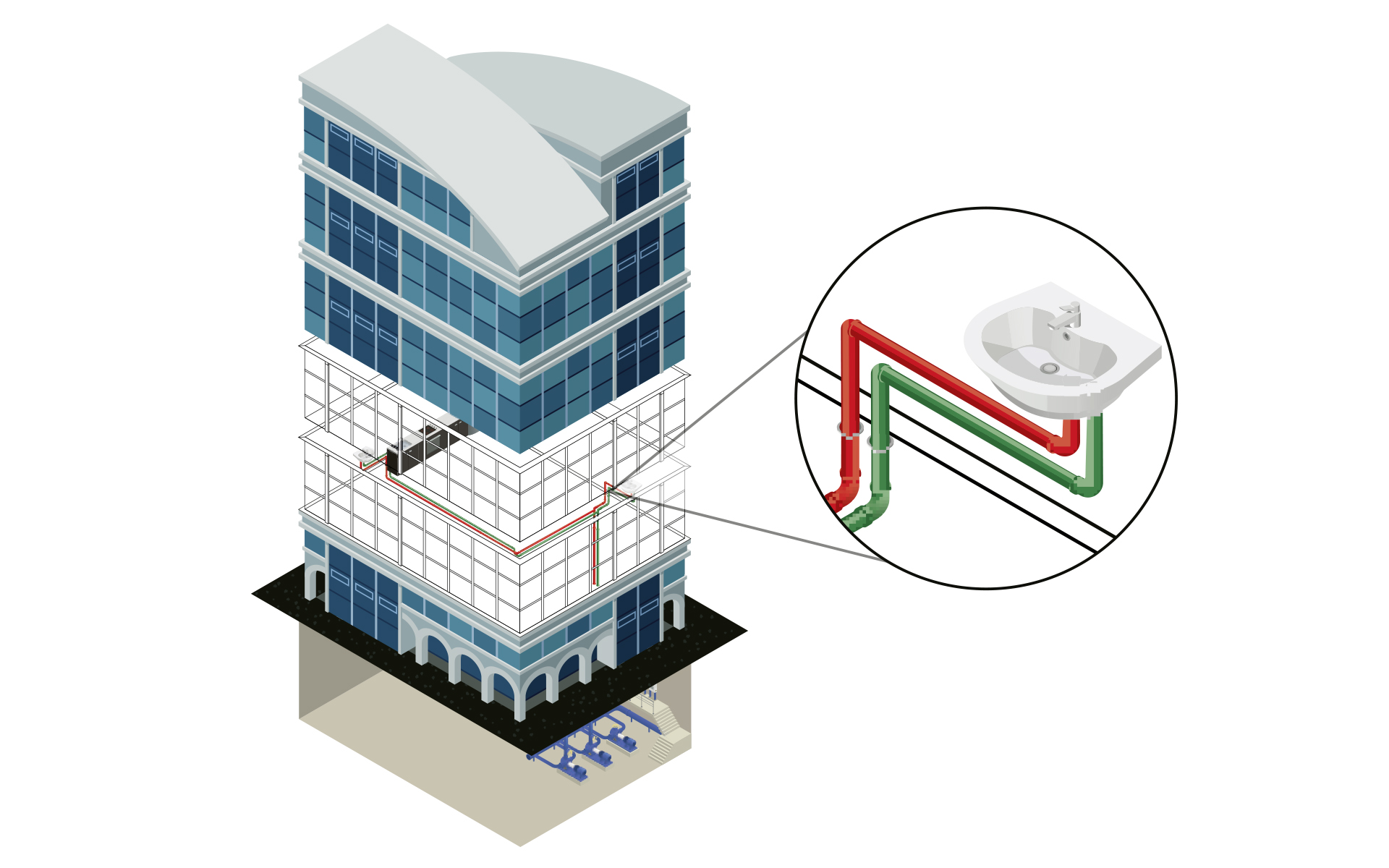
LINEAR workflow for potable and waste water design with Autodesk AutoCAD
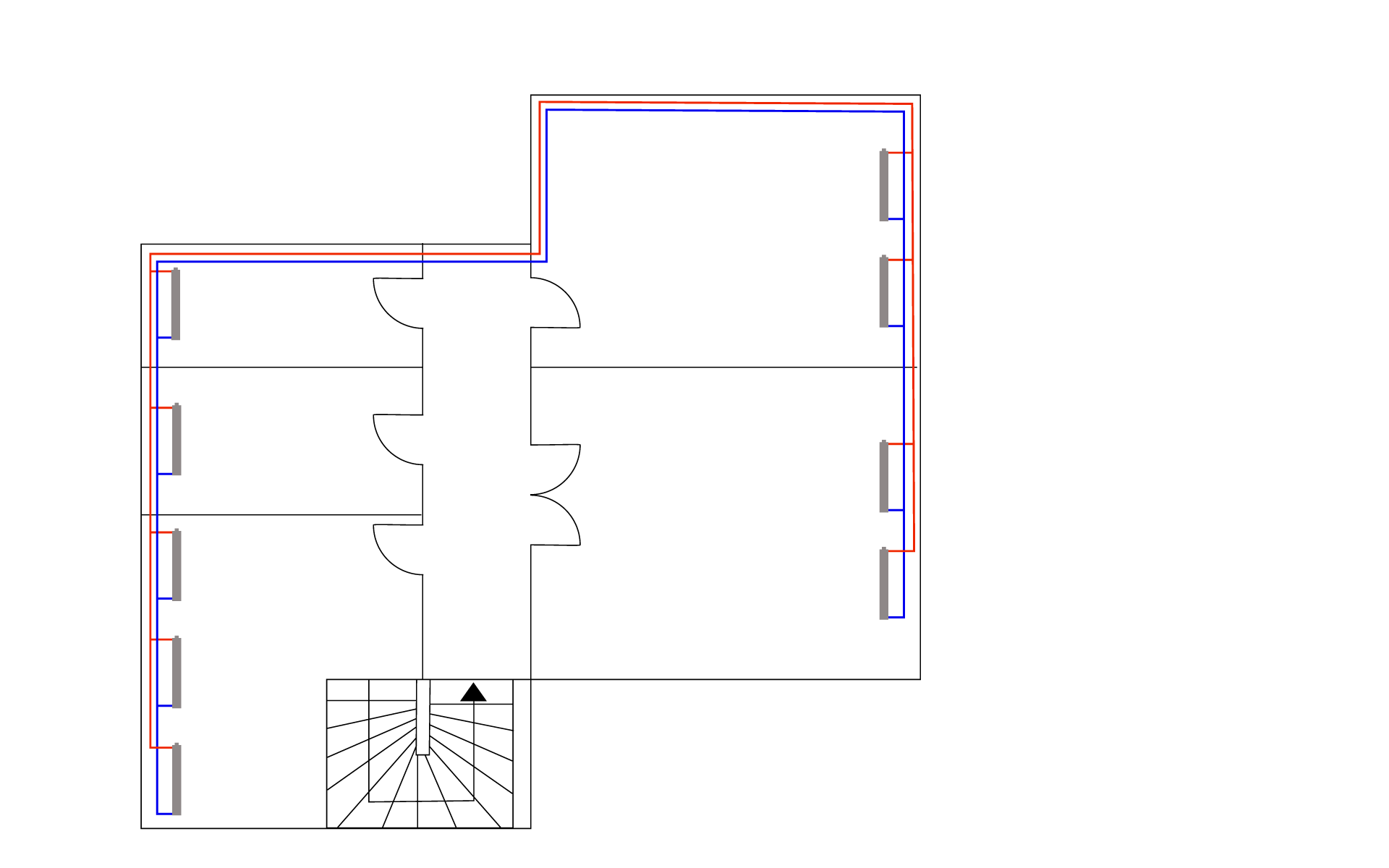
Schematic design

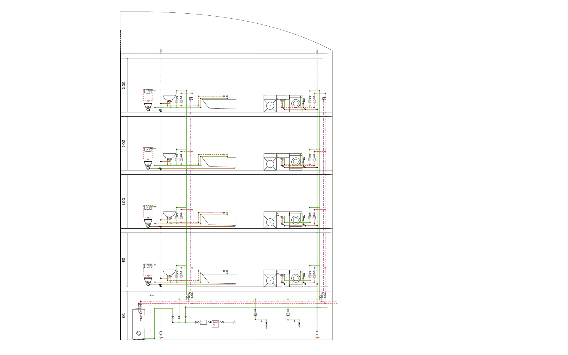
Input: Supply requirements for the building

Output: Calculable scheme design

Work steps:

  • Create storey table
  • Manual scheme creation with toolbars and specific editing commands
  • Scheme generator for drag and drop and automated drawing

Architecture as construction basis

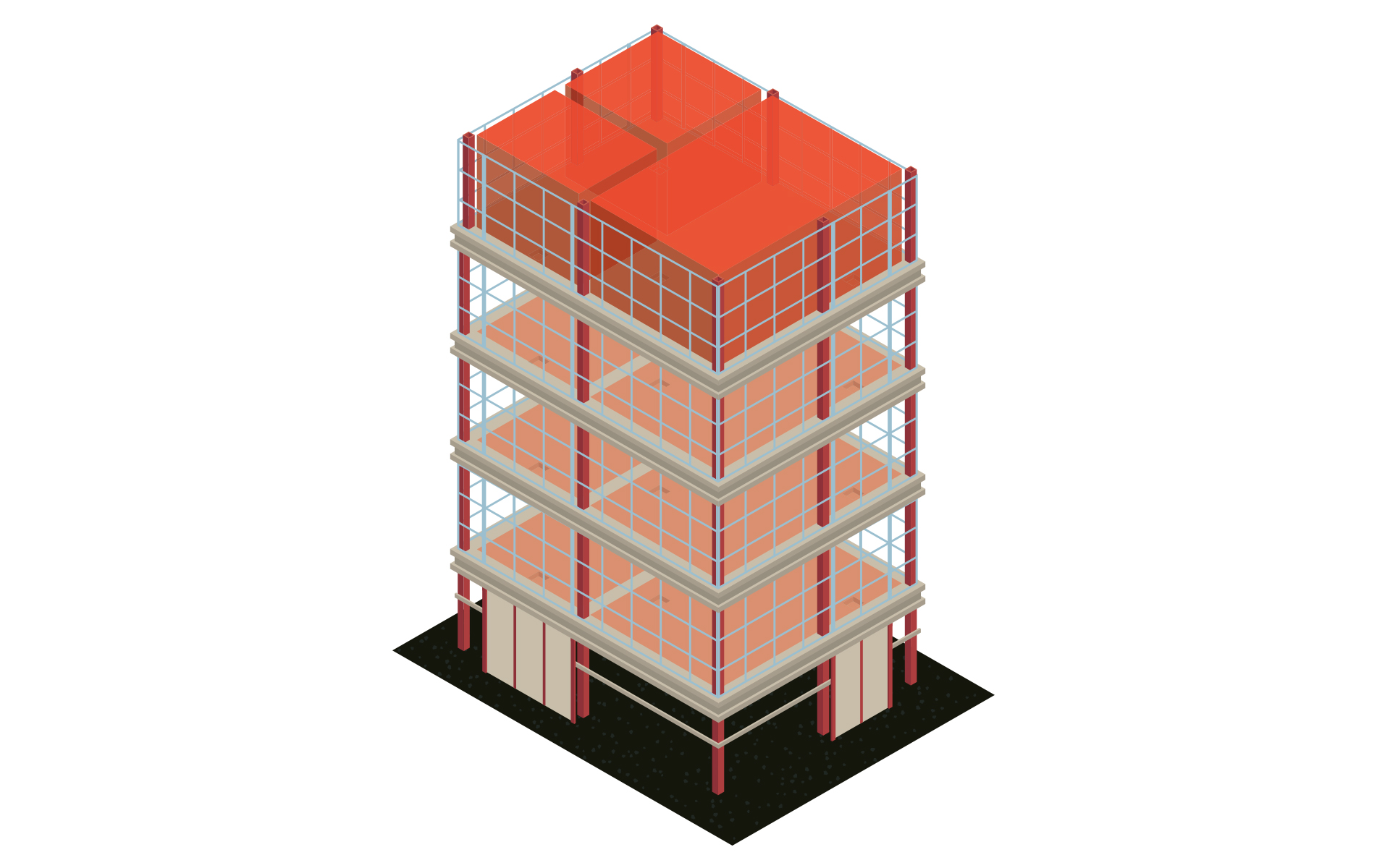
 Input: Architecture plan

Output: Model for further MEP design including levels and rooms

Work steps:

  • Referencing DWGs, DXFs or PDFs from the architect
  • Create storey table
  • Create and enrich the architecture with room data

Positioning of sanitary components

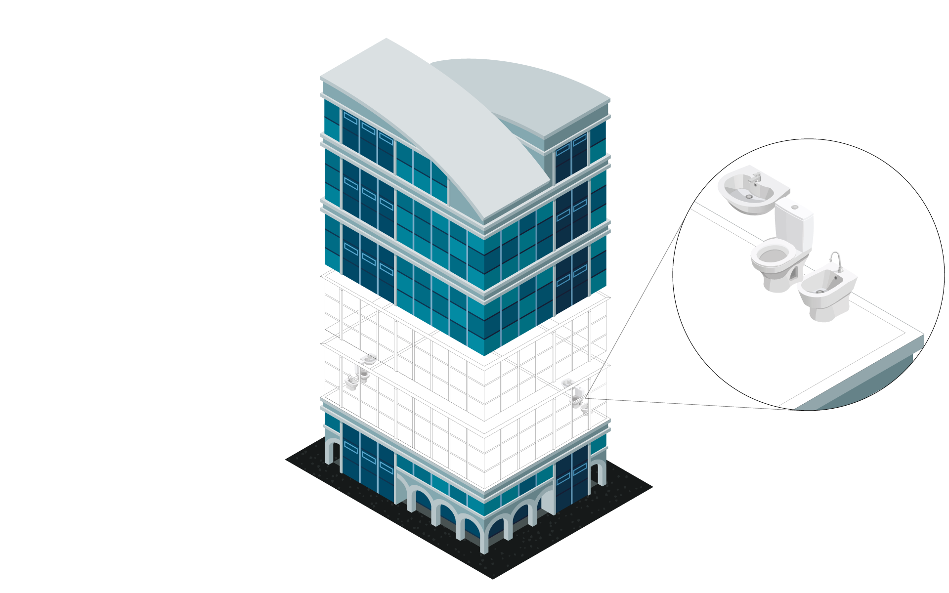
Input: Model for your MEP design including levels and rooms

Output: MEP model with sanitary components 

Work steps:

  • Selection of sanitary objects as neutral components or from the extensive manufacturer CAD libraries 
  • Easy placement in the model through specific drawing commands  

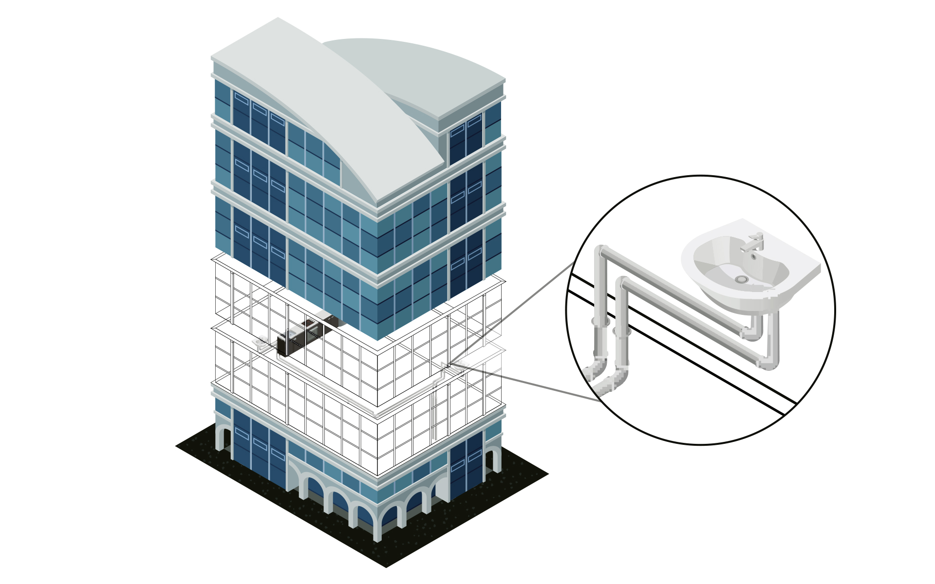
Create system in the isometry or floor plan

Input: MEP model with placed sanitary components

Output: MEP Model with a calculable network (isometric or floor plan)

Work steps:

  • 2D or isometric pipe network design using time-saving construction commands
  • Automatic connection of all consumers
  • Insertion of system components (e.g. house connections, filters, meters, fittings, separators, pressure boosting station)
  • System design in a neutral way or with the help of extensive manufacturer CAD libraries 

Create system in 3D

Input: Model for your MEP design including levels

Output: Detailed 3D model

Work steps:

  • Detailed pipe design
  • Automatic routing functions with preview of possible alternatives
  • System design in a neutral way or with the help of extensive manufacturer CAD libraries 
  • Subsequent placement of components with matching transitions and flanges
  • Automatic bolting of the entire construction (bolts, nuts, washers) with complete transfer to the parts list
  • Pre-define insulation materials and show/hide them with transfer to the parts list
  • Real-time collision check
  • Manually or automatically assigned item numbers
  • Material lists, parts lists with article numbers, sawing lists for pipes, position lists

Water network calculation

Input: Schematic, 2D or 3D model

Output: MEP model with optimized cooling system (schematic, 2D or 3D)

Work steps:

  • Specification of calculation-relevant specifications (e.g. assignment of pipe materials, settings of valves, specification of insulation and ambient temperatures).
  • Comparison of variants by using verified manufacturer data sets (e.g. pipe systems)
  • Calculation of existing networks by fixing individual or all dimensions
  • Simulation of ejection processes, check of comfort specifications and hygiene status
  • Automatic recognition of aeration ducts and types
  • Calculation of (gravity) drainage systems for rain and waste water inside buildings
  • Calculation of existing networks by fixing individual or all dimensions
  • Redimensioning of the water pipe network on the basis of the calculation
  • Colored display of all results directly in the model
  • Automatic 3D generation during system creation in 2D (step 5 - variant 1)

Labeling, output of model data and results

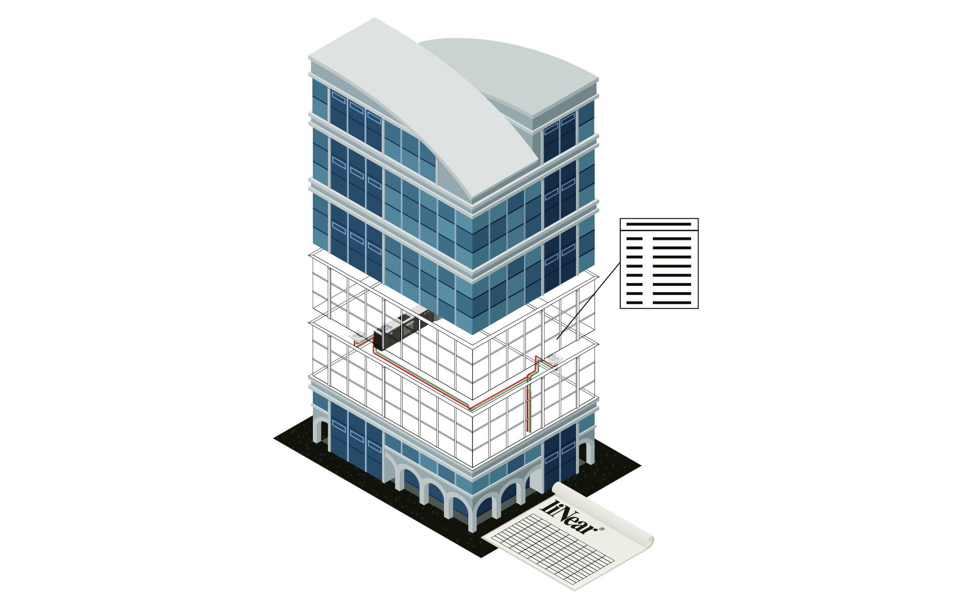
Input: Calculated and optimized water pipe network

Output: Final water design including model for transfer to the coordination model and calculated results incl. material lists

Work steps:

  • Saving of all inputs and calculation results in the model
  • Publication of selectable values as component data
  • Automatic labeling of the model
  • Addition of own parameters and meta information
  • Printout of the results in standardized forms 
  • Transfer of results and model in all relevant formats